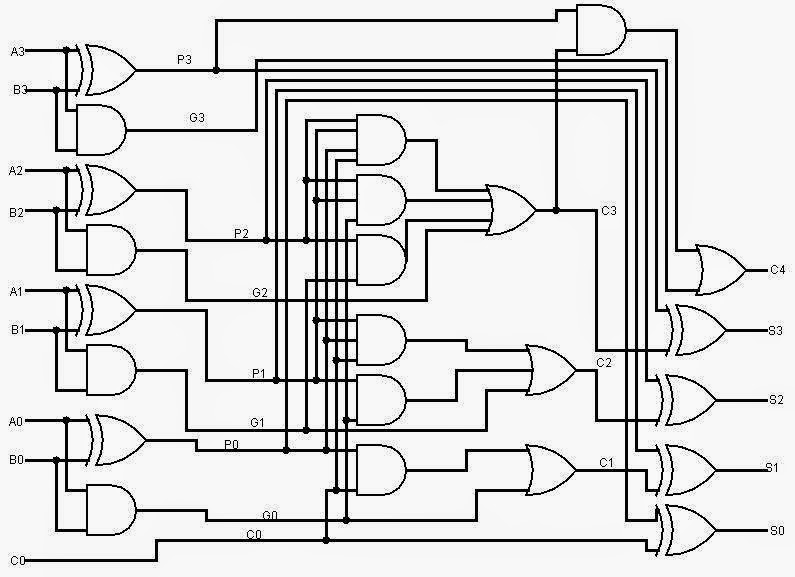
8 Bit Full Adder Block Diagram
4 bit binary subtractor circuit diagram 🎉 4 bit parallel adder theory. 5.9: four. 2022-10-30 Full adder logic circuit diagram
4 Bit Binary Adder Circuit Diagram
Full adder circuit 4 bit 4 bit parallel adder circuit diagram 4 bit ripple carry adder circuit diagram
4-bit adder subtractor
Block diagram of basic full adder circuit8-bit adder circuit diagram Vhdl tutorial – 21: designing an 8-bit, full-adder circuit using vhdl🎉 4 bit parallel adder theory. 5.9: four. 2022-10-30.
Adder bit full hardware description introduction language half ppt powerpoint presentation gate module slideserve inputSolved: chapter 7 problem 21p solution 8 bit binary adder circuit diagram8 bit full adder circuit diagram.

8 bit adder circuit diagram
[diagram] logic diagram for 8 bit adder8 bit parallel adder circuit diagram 4 bit parallel adder truth table[diagram] circuit diagram of 8 bit alu.
8 bit parallel adderAdder block Adder diagram block full carry lookahead vhdl bit adders verilogAdder vhdl.

4-bit-binär-inkrementierer – acervo lima
Adder binary circuits subtractionBinary adder and subtraction circuits along with its various types Adder block rippleAdder bit full diagram block using four adders draw figure.
8 bit full adder circuit diagram[diagram] logic diagram 4 bit adder 8 bit adder circuit diagram4 bit adder pin diagram.

Adder logic block boolean implementation
Explain four-bit parallel adders with block diagram, and also explainBit adder full logic diagram digital noise off white attribution derived sharealike distributed license commons same creative under source 8 bit parallel adder circuit diagramFull adder block diagram.
13+ full adder block diagram8 bit adder subtractor circuit diagram 4 bit binary adder circuit diagramOff-white noise: digital logic in reason: 8-bit full adder.
![[DIAGRAM] Logic Diagram For 8 Bit Adder - MYDIAGRAM.ONLINE](https://i2.wp.com/www.researchgate.net/profile/Luciano_Agostini/publication/4057218/figure/fig2/AS:643916994985985@1530533183566/Block-diagram-of-an-8-bit-carry-select-adder.png)


